RoboSub March 2025 Update
Software
Developing software for an AUV is a significant leap from the code we wrote for the SeaHawk II ROV last year. Luckily, our experience and existing codebase for the SeaHawk II meant most of our time was focused on the AUV specific additions, mainly computer vision and navigation. Of course, in order to properly navigate, we would need more sophisticated sensors as well as a simulation environment in order to sanity check our work.
Simulator
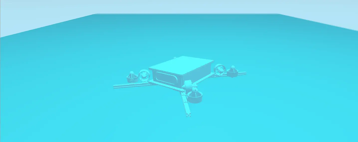
While LazerShark's hardware is still in development, our software team can validate code through simulation-based testing. We have integrated the Gazebo simulation platform into our ROS-based software stack, enabling software testing on a physically accurate virtual model of the AUV. The simulated vehicle and environment include custom buoyancy modeling, hydrodynamics, and various sensors. This approach allows for continuous development without a physical prototype or testing site, enabling software and hardware development to progress in parallel and rapid testing. So far, the simulator has allowed us to develop and validate the foundation of the navigation systems.
Sensor Integration
Just like us, robots have different "senses" to understand the world around them. Alone, our eyes may not provide a complete picture, but when combined with our other senses, we can accurately perceive what's happening. The LazerShark will be equipped with multiple sensors to achieve a comprehensive understanding of its environment, including a stereoscopic camera, depth sensor, inertial measurement units (IMUs), and a Doppler velocity logger (DVL). So far, we have written drivers for the IMUs and DVL. The IMUs provide information about the AUV's acceleration and heading, and the DVL allows us to measure the AUV's velocity and altitude. Given the sensor readings, an estimated pose of the robot is achieved through an Extended Kalman Filter (EKF).
Control Systems
In order for a robot to navigate through the world, a lot has to go right. Sensors have to be integrated to properly take measurements about the robot's movements, the cameras and the CV systems have to properly localize it in relation to its environment, and the EKF has to provide an accurate estimate of the robot's pose. However, once these parts are working properly, the question remains: how do we drive the robot's motors to navigate from one place to another? There are many different approaches, but ours relies on the field of Optimal Control Theory–specifically the Linear Quadratic Regulator. A Linear Quadratic Regulator, or LQR, provides an array of output (a twist, in our case) given the offset of the robot's pose from a desired pose. We chose an LQR over a simpler PID control scheme for a couple reasons. Mainly, a LQR allows us to model the dynamics of the robot, which is basically how the state evolves from a given state, as well as how it evolves according to the inputs provided. This allows us to account for the robot's drag, mass, and rotational inertias in the control systems. The second reason is the tuning parameters–as opposed to the PID controllers whose tuning parameters rely on repeated testing, the LQR's tuning parameters are fairly intuitive. They essentially represent how much to penalize errors in position versus large input values. Once the dynamics and weights are chosen, from a programmer's perspective, the work is done. For now, we simply have our control system navigating us from pose to pose in a straight line, which is essentially all you need for navigation in RoboSub. However, we do plan on improving the control systems to allow for more sophisticated paths, if time allows.
Computer Vision
Robots are a complex but elegant use of tools and engineering disciplines that help humans achieve tasks more efficiently, safely and effectively through an accomplished process of engineering. Computer vision acts as the eyes of a robot, allowing the robot to perceive its surroundings and coordinate the data through integrated software and hardware to its other components.
We have set up the NVIDIA Jetson as the primary edge computing platform for our project, this will allow us to leverage its GPU acceleration to run our own version of the YOLOV5 model for real-time object detection. We have been working on building a lot of OpenCV tools that will help us with preprocessing tasks such as image filtering, noise reduction, and edge detection. This will improve the quality of our input data for the model.
Our plan is to tweak and further develop a custom trained YOLOV5 model by gathering our own data from real world data collection and testing within the real world. To gather this data we will be using stereo vision footage from our ZED 2I camera and preprocessing the data with OpenCV, then using the data to fine tune the model to account for water distortion, object occlusions, and lighting inconsistencies. By combining the Jetsons hardware acceleration, OpenCV's tools, and YOLOV5 object detection capabilities, we will deploy a highly efficient and robust visual processing system that will be capable of real-time inference within dynamic underwater scenarios.
What's Next?
With basic navigation implemented, our goals are set towards completing the computer vision and path planning systems. Computer Vision is absolutely necessary for localization, and is by far the most crucial component we are missing. The addition of path planning algorithms will allow for the creation of more complex paths that can minimize distance while avoiding obstacles in unmapped terrain.
Electrical
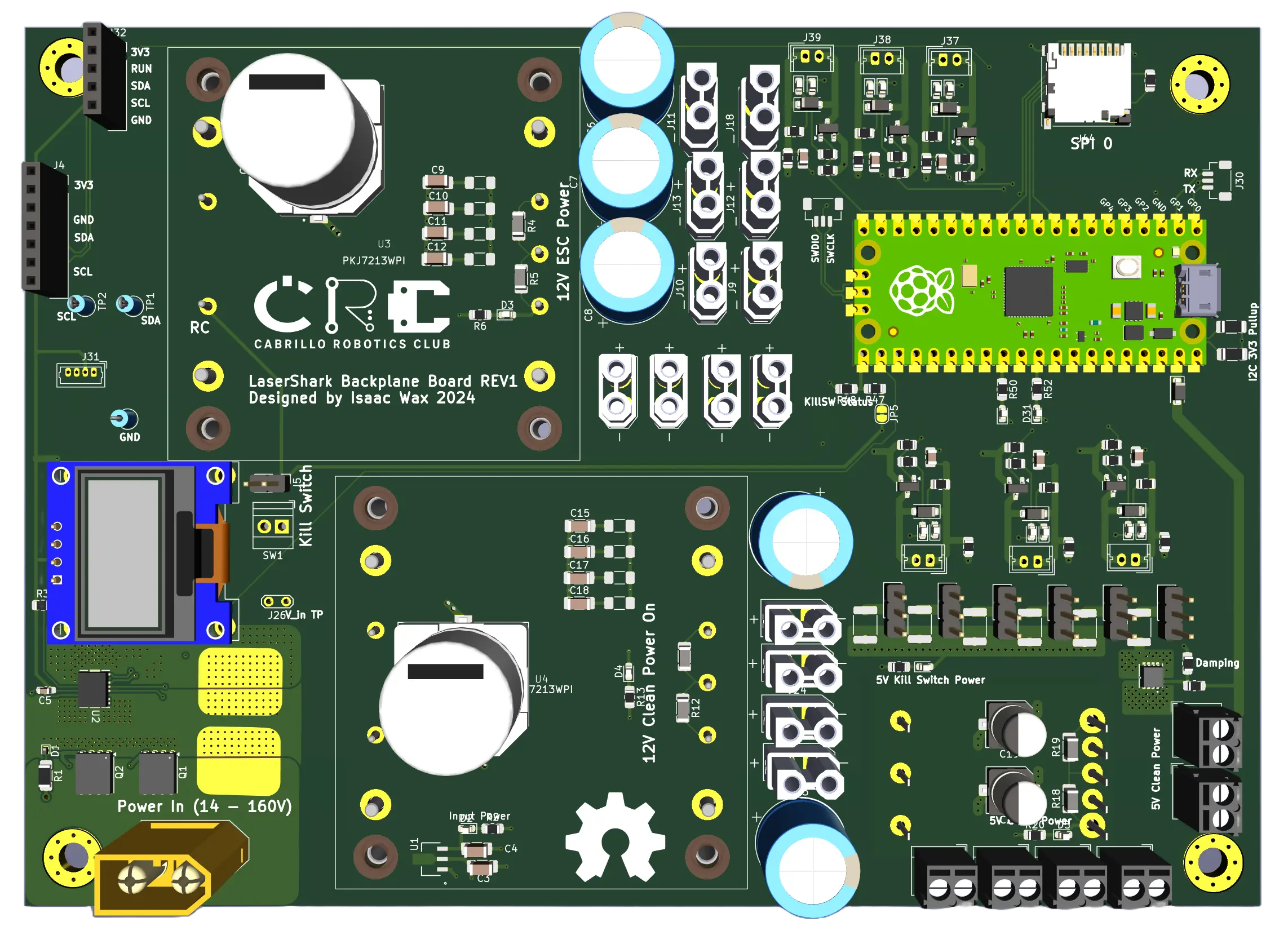
We have completed the design of the first revision of our Battery Management Board. The PCBs have arrived, and we are currently waiting for the components to begin assembly. While we wait, we are starting firmware development to enable energy consumption monitoring and environmental status tracking, including temperature, humidity, and SD card data logging
We look forward to assembling and debugging Revision A of the board. Once the BMS board is populated and we finalize our choice of Jetson, we will be able to assemble the full electrical stack. Additionally, we are making final decisions on the battery packs we will be using.
Mechanical
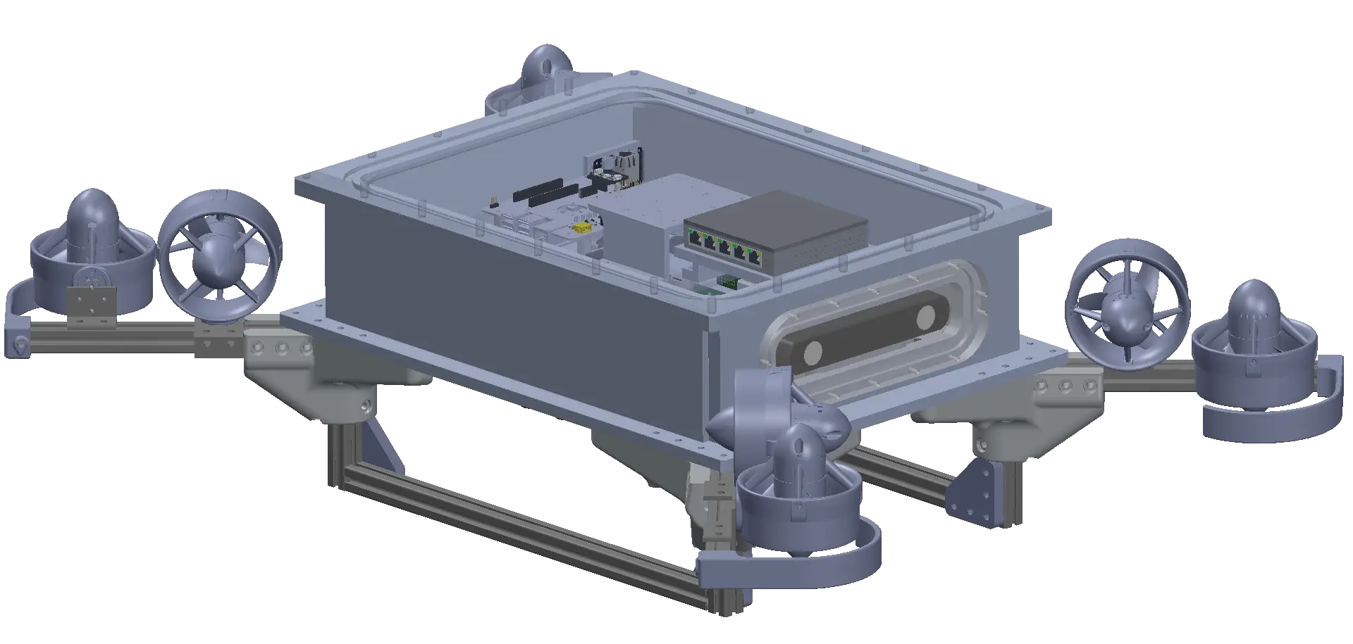
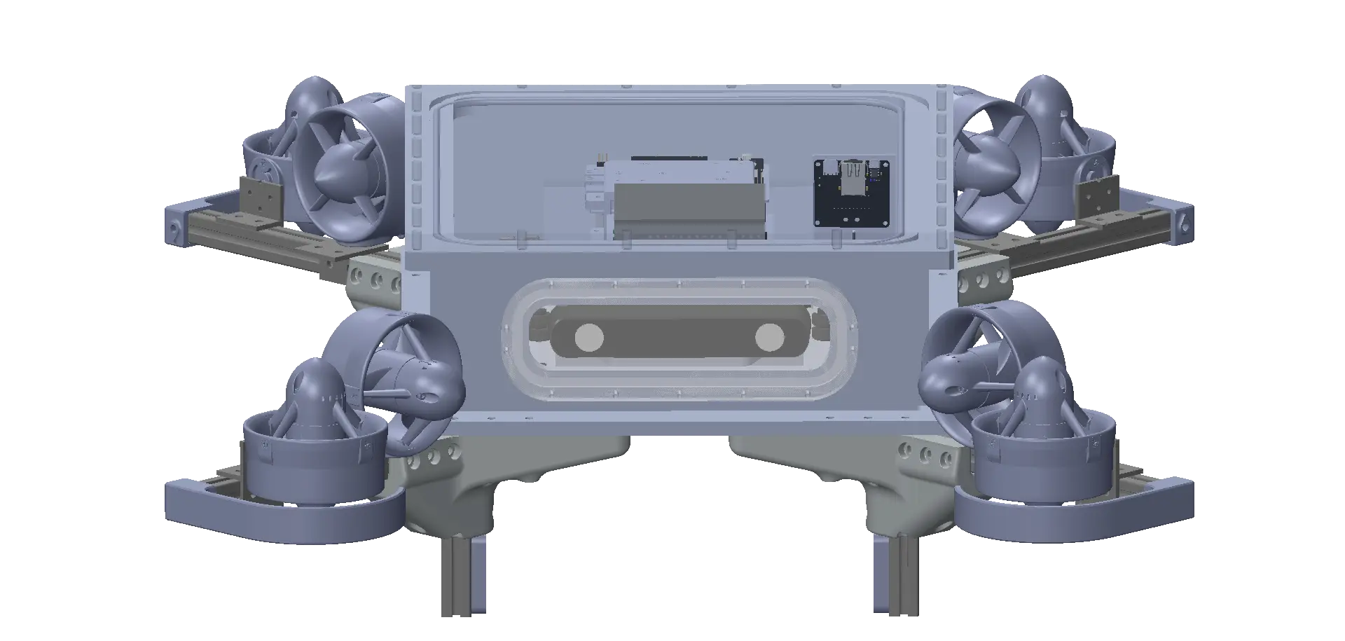
We are excited to announce that we have completed the manufacturing of our electrical box! We also just received a shipment containing all the mounting hardware and O-rings. Everything fits together quite well! A huge shout out to CITO Medical for allowing us to use their facilities to machine parts for our electrical box.
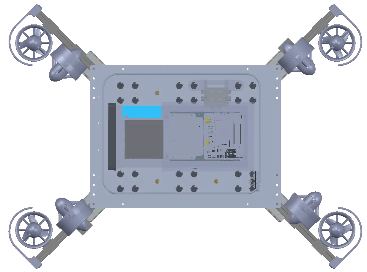
Currently, we are working on the internal layout of the electronics inside the electrical box and are designing the thruster mounts and a DVL mount for our chassis. These components attach directly to the electrical box. While some areas of our mechanical design still need refinement, the majority of the work is complete.
Battery Housing Design
One of our next major tasks is designing the battery housings. We delayed this step since we already knew the battery specifications we needed, but we were uncertain about the exact brand or whether we wanted to build custom battery packs. Now that we have that information, we can move forward with finalizing the design.
Computational Fluid Dynamics (CFD) Simulations
We are currently running CFD simulations to determine the linear drag coefficients in all directions for our LQR (Linear Quadratic Regulator) control system. Using SolidWorks CFD, we have been solving for the rectilinear drag coefficients and are now developing a computational method for solving rotational drag coefficients.
Because our vehicle consists of a mix of unusual materials and has a highly non-uniform structure and we require an accurate center of mass measurement we have decided that we can not trust values from our CAD. We are opting for physical measurements rather than purely computational estimates. We are currently developing fixtures and testing procedures to measure the center of mass and the moments of inertia for LaserShark.
Final Assembly and Pool Testing
We are still waiting on a significant amount of shipments, including penetrators and electrical connectors. Once these arrive, we can complete the assembly of our chassis and electrical box. With the electronics nearing integration, we are aiming for our first pool test within the next six weeks!
Outreach
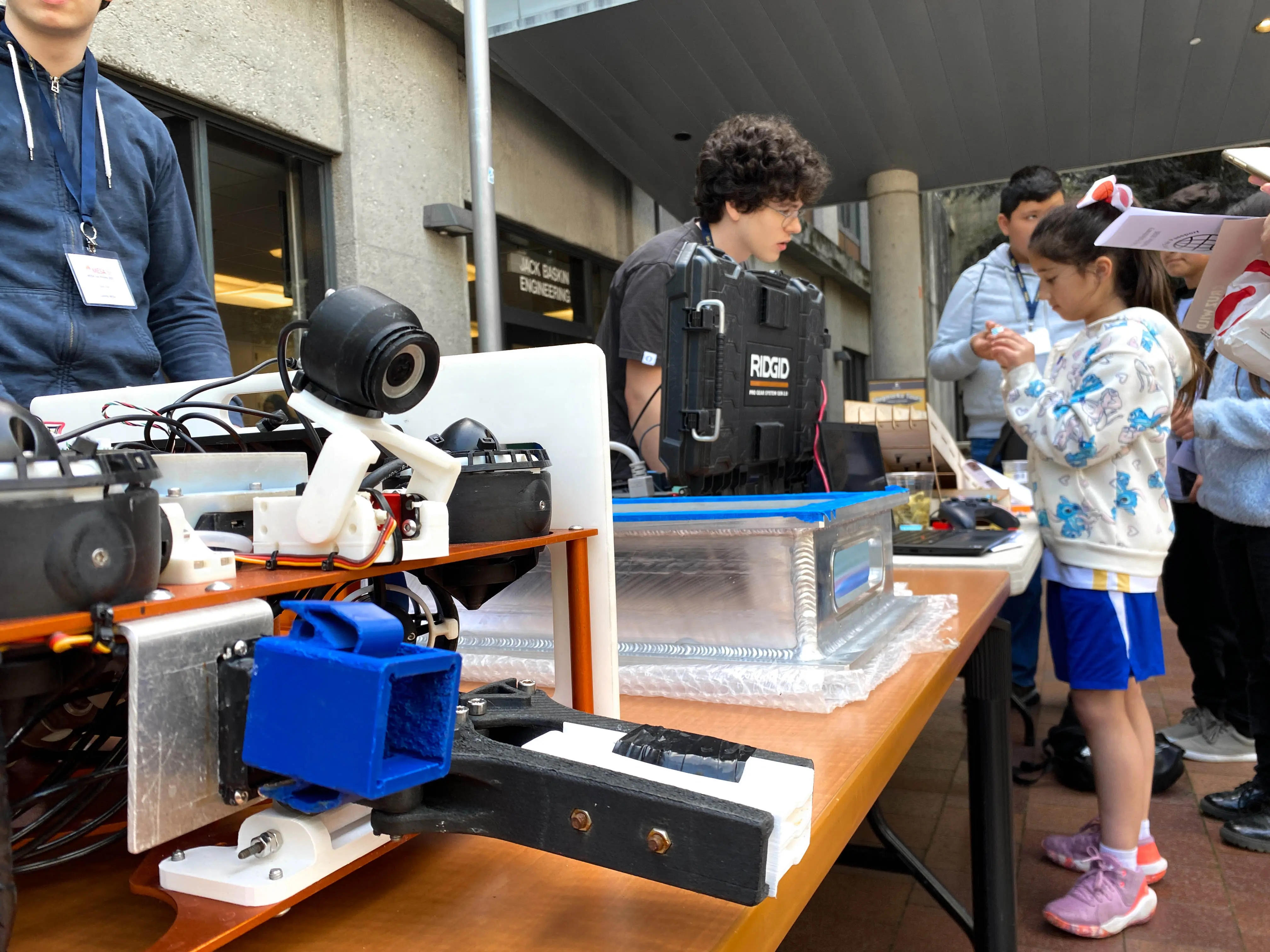
The Cabrillo Robotics Club recently participated in MESA Day at the University of California, Santa Cruz, an event that brought together over 250 middle and high school students from Santa Cruz and neighboring. Throughout the day, students engaged in hands-on activities and connected with industry professionals and STEM organizations, including our club. We showcased our SeaHawk II and LazerShark robots and led an interactive bristle bot activity in which students got to build and race simple bots.
Sponsors
Thank you to the individuals and organizations who have generously supported us in constructing LazerShark. We give our thanks to PNI Sensor for providing us with their NaviGuider and TargetPoint-TCM IMUs. It has been great working with PNI, they have been very responsive and helpful and we are proud to be using their products. We are also incredibly grateful to Water Linked for giving us a generous discount on their A50 DVL. This sensor is a crucial part of our AUV and has provided us with impressively accurate readings. We are also thankful to CITO Medical for allowing us to use their facilities to machine our electrical housing. Lastly, we thank Cabrillo Engineering Department alumnus Mark Cowell for funding our RoboSub competition registration. There are many other organizations and individuals we have to thank for contributing to the funding of the project, please visit our sponsors page for more details. Your generosity is greatly appreciated and we could not do what we do without you.


